A PROFESSIONAL DIGITAL CAMERA
by John Henshall
Think of high-end portable professional digital cameras in 1999 and just one manufcturer would spring to mind: Kodak.This article explains how Kodak digital SLR cameras were made.
The
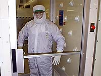
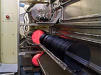
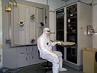
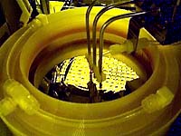
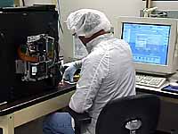
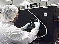
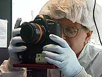
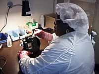
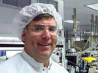
Micro Technology Division A typical office has around 100,000 particles of dust per cubic metre. Kodak's camera assembly area reduces this by over ninety percent but the silicon chip manufacturing areas need even higher dust control and so requires the use of a special suit, helmet, visor, gloves and shoes which completely enclose the body. Workers at the plant have to spend twelve hours per shift in this garb. Here you see me enjoying a cold air shower to remove any remaining particles -- for example from my hands during dressing. These are
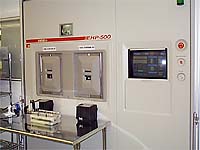
wafers on the new six inch line waiting to be baked
in the furnace tubes at 800 degrees Celsius. Here
you see the top tube full and closed, the middle
and bottom tubes waiting to receive racks of
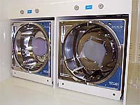
wafers. These
machines, which look like high-tech versions of
domestic clothes washing machines, are indeed for
rinsing and spin drying the wafers. My flash has
stopped the wafers in mid spin. I once
thought that digital imaging was 'green' but it's
manufacture uses many extremely toxic chemicals and
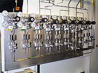
gases. Special plumbing is used to control and
monitor gases and sensors throughout the plant warn
of any leaks, no matter how small. Saftey and
responsible handling is of paramount importance.
There is no doubt that these substances are best
dealt with by an experienced chemicals company -
which is exactly what Kodak is - leaving no
residual chemicals for users to dispose of and
ensuring that digital capture is environmentally
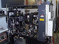
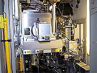
friendly. Half a
megavolt resides inside this menu driven Varian
EHP500. This fine
pattern aligner is capable of achieving a level to
level accuracy of 0.1 micron -- compare this with
the 5 to 10 microns width of a typical CCD
pixel.
|
MAKING
THE CAMERAS |
 |
|
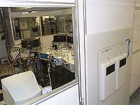
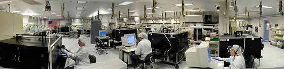
Kodak's Digital Capture Manufacturing Facility is a purpose-built assembly area for professional digital cameras. It's here that all Kodak's professional DCS range is made -- currently the DCS315, 330, 520, 560, 620 and 660. |
|
|
|
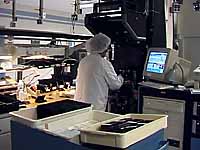 |
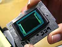
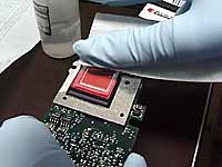
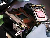
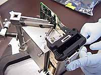
Raw CCDs are received from the wafer fabrication department, the Micro Technology Division (MTD). Here they are attached and critically aligned to a metal plate, which is the key reference point which determines the accurate positioning of the CCD in the film plane. |
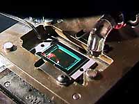 |
The CCD is aligned precisely in seven axes -- left/right, up/down, top left, top right, bottom left, bottom right and skew -- before being tacked in position with an adhesive which cures in 45 seconds. This fixes the CCD sufficiently to proceed to the next step but not enought to withstand shock in the field. |
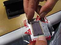 |
Static-free tape is used to create a dam, between the metal plate and the imager ceramic, into which viscous Stycast epoxy is flowed. The tape prevents the epoxy from spilling out the other side. The Stycast is cured for eight hours. This not only fixes the CCD permanently but also prevents dust getting onto the imager face. |
 |
(X) |
 |
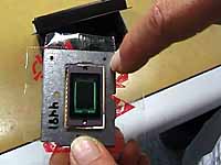
Once the the Stycast has been flowed in and cured, the space between the CCD and the reference plate is completely filled. The relationship of the plate and CCD is fixed forever. |
 |
(X) |
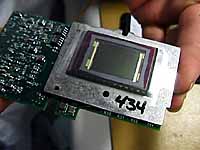 |
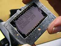
The imager plate is now mounted onto the main camera board … |
 |
… through which the CCD pins protrude. These are now soldered into position. |
 |
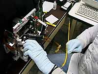
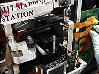
The mounted imager now moves to the Defect Mapping area … |
 |
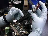
… where it is first cleaned with alcohol … |
 |
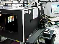
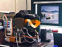
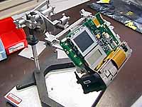
… then placed on an exploded camera body mounted on a test fixture. |
 |
(X) |
 |
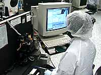
This rig makes a series of images of a 1,000 foot candle light source. These are evaluated by a computer program on a pixel by pixel basis, checking that all the pixels and columns are present . The output of each pixel is plotted, any differences being written to a file which will be stored permanently in the camera and used to even out these small variations on a shot-by-shot basis. |
 |
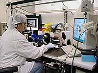
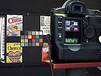
The imaging assembly then moves on to this station for Colour Calibration. |
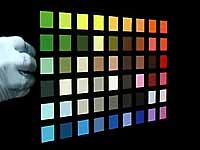 |
This is achieved by exposing a colour chip chart illuminated by daylight, tungsten and flourescent colour temperature light and comparing the values obtained by the imager again known fixed values. |
 |
(X) |
 |
The image on the LCD at first looks quite a bit different from the chart. If the red is too bright, or the blue too dark, another computer program writes an alogithm which will correct those deviations. This is written to the image file created in the Defect Mapping area. |
 |
(X) |
 |
The imager is now ready to be installed in the image plane of a camera body, assembled in another part of the facility. |
 |
(X) |
 |
The imager is now ready to be installed in the image plane of a camera body … |
 |
(X) |
 |
… where it is fixed in place. |
 |
(X) |
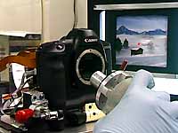 |
Next, the camera's shutter is locked open and a probe is fixed into position in the lens mount. |
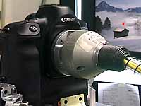 |
This measures the position of the imager relative to the lens mount. This is the final check that all the tolerances in the Kodak components, ensuring that these stack up in the right direction. To ensure compatibility between components, no adjustment is made to the lens mount. |
 |
Although Kodak DCS cameras are based on established 35mm film camera bodies, new parts have to be made, either by the camera manufacturer or by Kodak -- as in the case of these magnesium castings for the Nikon F5 based DCS620 and 660 range. |
 |
In the case of the taller DCS6XX cameras, the main board is mounted inside the new Kodak casting. |
 |
() |
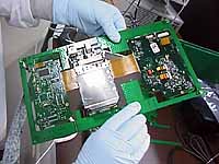 |
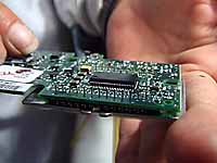
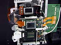
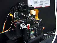
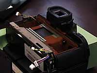
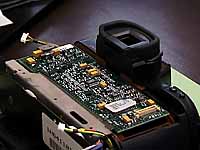
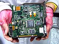
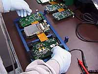
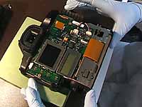
The design of the more squat Canon EOS-1n bodied DCS520 and 560 is somewhat different. These are the three boards as manufactured, held together by a (green) frame so that the (brown) inteconnecting cables do not get damaged. The PCMCIA card drive is the silver rectangle in the middle. This will lie across the base of the camera. |
 |
The other side of the board shows the two LCD panels (colour and monochrome) at the top. |
 |
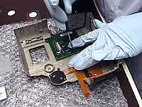
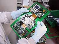
The boards are broken out of the frame by hand … |
 |
… leaving the three boards connected by the interconnecting cables. These are hard-wired, so they do not have any connectors to cause problems. |
 |
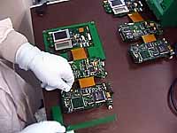
The boards are mounted into a jig (blue) which holds them in position for testing. Care must be taken to avoid damage to the delicate cables. |
 |
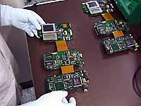
This is mounted onto a camera body test fixture and plugged-in to simulate the cables in the camera. |
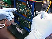 |
Finally it is hooked up to a computer and the FireWire connection is made. |
 |
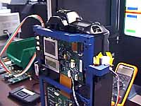
Once checked, the boards are wrapped around the base of the camera on a jig. to form a 'brick'. Note the way that the cable wraps around to connect the boards. |
 |
Here we see the PCMCIA card slot, the tripod bush and, at the bottom of the picture, the cable curving onwards to the third (concealed) board. the FireWire and power connection are at the opposite end of the base of the camera. |
 |
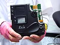
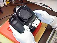
We now reach 'camera complete' where the 'brick' is installed in the camera body behind the imager board. |
 |
The back cover of the camera is secured in place by nine screws. |
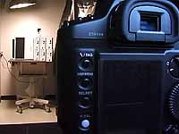 |
It's now time to make more checks. First, focus alignment. The targets in this station are captured in various positions in the viewfinder to check focus across the field. |
 |
System verication for image quality to verify exposure and linearity of colour balance. |
 |
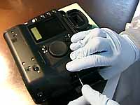
When everything has been checked once again, it's time for "button up", the final step in the assembly process. It's here that the final screws are put in place … |
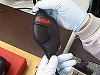 |
… the strap is laced into place … |
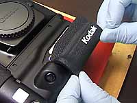 |
… and the Kodak pedigree applied. |
 |
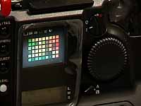
But still there are more checks, this time as 'real' shots … |
 |
… pointing at these charts and colourful packs. |
 |
() |
 |
With everything assembled, checked, double-and triple-checked it's time for a loving final clean and polish by Blanche. (I wish she was constantly available to clean my nose prints off the LCD screens!) |
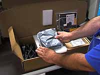 |
… before the cameras are packed, together with instruction booklet, software, batteries, charger, power supply and cables. |
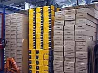 |
Finally, the cameras are ready for shipping. The yellow boxes are for Kodak customers, the others contain the D2000 variant of the DCS520 for delivery to Canon. |
 Kodak's Jerry Magee |
Special thanks to Peter Jameson, Vince Andrews, Steve Noble, Jerry Magee, Michael McCreary, Herb Erhardt, Tony Eatough, Diana Wong, Michael Troncale, Anthony Sanzio. For further information about Kodak Professional Digital Cameras see www.kodak.com/go/professional For general information about The Eastman Kodak Company see www.kodak.com |
|
The images in the Digital Capture Manufacturing Facility were photographed in available light using a Sony DCR-TRV900 digital video camera. The still frames were captured from the DV tape using a FireWire card and PhotoDV from Digital Origin (formerly Radius Inc.) The images in the Micro Technology Division were photographed using a Kodak DC220 digital camera which had bee specially cleaned to use in the dust-free environment. All images were captured on 30 September 1999 in Rochester, NY, USA. |
This is an extended version of the article which first appeared as "John Henshall's Chip Shop" in "The Photographer" magazine, November 1999.
IMPORTANT NOTICE
This document is Copyright © 1999 John Henshall. All rights reserved.
This material may only be downloaded for personal non-commercial use.